4-Terminal Sensing for Real-Time Data Logging Using a Microcontroller
4-terminal sensing is slightly more complicated to set up than 2-terminal sensing and less compact in implementation. However, it is more consistent between sensors and more repeatable for a given sensor. It virtually eliminates the effect of contact resistance and other input resistances on the measurement of a resistive sensing element.
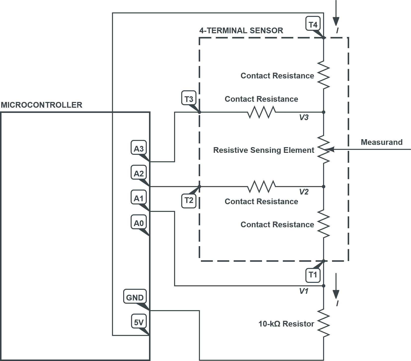
\(\uparrow\) The wiring diagram showing the interface between a sensor with conductive traces for 4-terminal sensing and a microcontroller, of which A0 – A3 are analog input pins. The microcontroller is programmed by and sends data – namely, the resistance of the sensing element within the conductive traces – to a computer, via USB over serial communication.
Materials and Preparation
A computer with the Arduino IDE (recommended) installed
A microcontroller with at least 3 analog input pins, such as an Arduino (recommended) Uno or Nano, and its USB cable
A sensor with conductive traces for 4-terminal sensing
A 10-kΩ or similar through-hole resistor of known value
For Testing and Evaluation Purposes…
5 lengths of solid core hook-up wire with stripped ends
5 insulated crocodile clip jumpers (double-ended)
For Production without a Circuit Board…
5 lengths of solid core hook-up wire with stripped ends
Soldering setup
Soldering iron with stand
Lead-free solder
Soldering sponge or similar
5 pieces of thin heat shrink tubing
4 lengths of thin (e.g., 30 AWG) wire with stripped ends
Conductive paint syringe
Masking tape
Instructions – Assembly

WARNING: Exercise extreme care when handling or using a soldering iron. Always assume that it may be plugged in and hot. Only those who are familiar with the safe use of a soldering iron should attempt to use it. Failure to follow proper practices may cause up to third degree burns.

Caution: Do not connect the voltage input pin (Vin) or voltage output pin (5V) pins of your microcontroller to its electrical ground (GND) pin. Failure to follow this instruction will potentially result in permanent damage to the microcontroller and any connected devices.

\(\uparrow\) Pinout of a 4-terminal sensor.
For Testing and Evaluation Purposes…
Connect your hook-up wires to the
GND,A1,A2,A3, and5Vpins of your microcontroller.Connect your crocodile clip jumpers to the hook-up wires.
Connect your resistor midway through the
A1wire assembly.Connect the end of the
GNDwire assembly to the resistor.Connect the ends of the remaining wire assemblies, in order, to terminals
T1–T4of your 4-terminal sensor.
For Production without a Circuit Board…
Connect your hook-up wires to the
GND,A1,A2,A3, and5Vpins of your microcontroller. Slip on your heat shrink tubing if necessary at this point.Solder your thin wire to the latter 4 hook-up wires.
Solder your resistor midway through the
A1wire assembly.Solder the
GNDhook-up wire to the resistor.Apply the heat shrink tubing around all connections by evenly heating it using your soldering iron.
Connect the ends of the remaining wire assemblies, in order, to terminals
T1–T4of your 4-terminal sensor.Coil the stripped ends of your thin wires into loops.
Carefully rest the loops on the center of the matching terminals’ contact pads, holding the wires and sensor down using masking tape.
Carefully cover the wire loops with conductive paint within the borders of the contact pads.
Wait for your conductive paint to fully dry/harden.
See also Using Conductive Paint and Preparing Electrical Contacts.
If you are using an Arduino microcontroller, open its IDE on your computer and plug in your board using its USB cable.
Instructions – Programming
If you are using an Arduino microcontroller, upload the following code to it using the its IDE, after which it will begin running onboard.
float R_series = 10e3;  // Known value of resistor in series with 4-terminal sensor.

float V_1;
float V_2;
float V_3;

float I;
float V_elem;
float R_elem;

void setup()
{
    Serial.begin(9600);   // Open communication with a computer via USB or with another device via UART.
}
void loop()
{
    V_1 = analogRead(1);  // Measured voltage across series resistor.
    V_2 = analogRead(2);  // Measured voltage looking into the 4-terminal sensor at terminal `T2`.
    V_3 = analogRead(3);  // Measured voltage looking into the 4-terminal sensor at terminal `T3`.

    I = V_1 / R_series;   // Calculated current through both series resistor and 4-terminal sensor.
    V_elem = V_3 - V_2;   // Calculated voltage across sensing element.
    R_elem = V_elem / I;  // Calculated resistance of sensing element.
If you are using the Arduino Serial Plotter, append the following code.
    Serial.print("R_sens:");
    Serial.print(R_sens);
    Serial.print("\t");

    Serial.print("lower:");
    Serial.print(0);
    Serial.print("\t");

    Serial.print("upper:");
    Serial.print(10e3);
    Serial.print("\r\n");
}
Or download the complete sample code: 4_Terminal_Sensing_for_Real_Time_Data_Logging_Using_Arduino_Serial_Plotter.ino
If you are using the Arduino Serial Monitor, append the following code.
    Serial.println(R_sens);
}
Or download the complete sample code: 4_Terminal_Sensing_for_Real_Time_Data_Logging_Using_Arduino_Serial_Monitor.ino
Additional Resources
Communication – Serial
Analog input/output – analogRead()
Real-Time Data Logging
Use the Arduino IDE Serial Plotter (online reference) to visualize live data over a recent period of time.
Use the Arduino IDE Serial Monitor (online reference) to write live timeseries data that can be copied and saved. Disable its Show timestap option beforehand.
In either case, set the baud rate to “9600 baud” to match the Arduino code and the line ending to “Both NL & CR” beforehand.
The Arduino serial plotter and monitor cannot be used simultaneously.