Calibrating Your Accelerometer
From the force gauge, an accelerometer can be constructed by adding a proof mass to the end of the cantilever. In this guide we will be instructing how to print and calibrate a functional accelerometer. This accelerometer will have the ability to measure the proportion of gravity experienced as it is rotated.
Materials and Preparation
An accelerometer of the following design characteristics. An untested accelerometer with these defaults can be found from
mid_str_4T_sensing_and_elem.SLDPRT.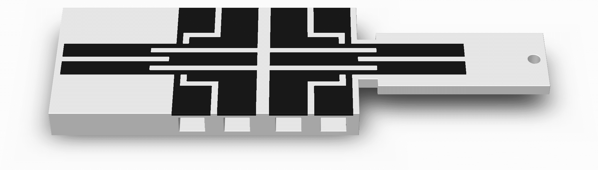
A known proof mass at to the end of the cantilever beam. A metal ball can be mounted in the proof mass slot to increase the sensitivity of the sensor.
A relatively thick cantilever base to avoid unwanted deflection, emulating being embedded into your comparably large parent 3D printed structure. If you would prefer to lessen your print time, the cantilever can be glued to a piece of wood to act as the base.
A reference set of conductive traces to correct for changes in temperature and humidity
4-terminal sensing in each set of conductive traces
Large electrical contact pads
Spaces for the lower jaws of the crocodile clips (optional)
An insulated double-ended crocodile clip jumper (or conductive paint/epoxy and lengths of thin wire stripped of their insulation on both ends) for each electrical contact- A computer with the Arduino IDE (recommended) installed
A computer with the Arduino IDE (recommended) installed
A microcontroller with at least 1 analog input pin, such as an Arduino (recommended) Uno or Nano, and its USB cable
A sensor with conductive traces for 2-terminal sensing
Three potentiometers of magnitudes containing the range of your sensing element
A test station that can perform a tumble test. See here for instructions on preparing a suitable test station.
2 lengths of solid core hook-up wire stripped of its insulation on both ends
2 insulated crocodile clip jumpers (double-ended)
A dividing head to perform the tumble test, please see Performing the Tumbling Test for more information. A sample model and additional instructions can be found in Printing the Tumbling Test Rig
A mounting method to affix the accelerometer to the dividing head
Instructions
Mount your clamp/vice on a table as shown above.
Clamp onto your force sensor’s cantilever base without the conductive traces being touched as shown above. Leave room for your crocodile clips if you are using them, room for the cantilever beam to bend downward, and room to suspend your weights from the cantilever beam’s free end.
Tie your string or spare wire securely to the free end hole as shown above. Ensure that its mass is nearly 0 grams beforehand.
Tie a loop at the other end of your string or spare wire.
If you are not using weights with hooks, hang a lightweight clear plastic pouch from the loop to hold them as shown above but without its weights. Ensure that its mass is nearly 0 grams beforehand.
Clip one end of your crocodile clip jumpers into the terminal slots, onto the surfaces of the electrical terminals as shown above (or follow the instructions in Preparing Electrical Contacts).
Prepare the mount for the accelerometer, the accelerometer should be mounted to the dividing head such that the sensing direction be perpendicular to the axis of rotation.
Performing the Tumbling Test
This guide is intended to assist in printing the tumble test. As per IEEE Std 1293-2018 12.3.12, a 4-point tumbling test is performed to measure temperature hysteresis. From this test the accelerometer characteristics can be determined at varying temperatures.
Note: Accelerometer performance is commonly influenced by temperature, including 3D printed sensors.
The procedure for a tumbling test is as following:
Record the temperature of the test environment
Rotate the dividing head to the 90° position (input reference axis up). Record resistance output by the accelerometer output as E90.
Rotate the dividing head to the 270° position (input reference axis down). Record resistance output by the accelerometer the accelerometer output as E270.
Rotate the dividing head to the 0° position (input reference axis horizontal). Record the resistance output by the accelerometer the accelerometer output as E0.
Rotate the dividing head to the 180° position (input reference axis horizontal). Record the resistance output by the accelerometer the accelerometer output as E180.
Plot the resistance against the angle to generate the characteristics of your accelerometer as it is rotated
Plot the normalized resistance against the angle.