How To Prepare and Print a Capacitor with Cura
With Pithon’s customizability, there are two options on how to print:
Print original Monti provided capacitor
Customize the original capacitor to your liking before printing
These options will be outlined below.
Print original Monti provided capacitor
Step 1 Since the parallel plate capacitor requires high resolution and precision, it is recommended to freshly reload filaments before printing. This can be done by:
Navigate to SYSTEM on the Ultimaker 3, then to the extruder of your choice, and Unload
Once the unload process is finished, lift the material clasp to release the filament. There may be a part of the filament which is tapered and not uniform as the rest. Use common scissors to remove this part before reloading.
Reload the filament by going to SYSTEM on the Ultimaker 3, then to the extruder of your choice, and Load.
When prompted to select filament, choose the filament which best describes the material used. In Monti’s designs, both materials are PLA based.
Allow for the filament to be loaded and wait for a constistent strand of filament to be extruded. Do not stop the process until the filament has reached at least 15 cm below the print head.
Perform these steps on both materials
Step 2
Navigate to files to find UM3E_Parallel Plate Cap C3-2 (1cmx1cm).gcode and UM3E_Parallel Plate Cap C3-2 (1cmx1cm).mf.
Step 3
Communicate files to the printer. Ultimaker allows for communication over LAN or USB.
For LAN communication
Connect Ultimaker 3 to your network via WiFi or ethernet connection.
For WiFi, navigate to SYSTEM menu and select. Then choose NETWORK, followed by Run WiFi and follow on-screen instructions.
For Ethernet, connect an ethernet cable into the LAN port located on the rear of the printer.
Select the method of the above chosen methods in NEWORK on the printer.
On Ultimaker Cura, in the menu bar along the top, select Settings, Printers, then Manage Printers.
Select Connect via network in Cura.
Select the printer you hope to use and select Connect.
Load
UM3E_Parallel Plate Cap C3-2 (1cmx1cm).mfas an Ultimaker project.Slice print by selecting Slice in a blue bar in the bottom right of the screen.

Select Print over network to print.
For USB communication
Find USB intended for use and insert into USB port on the user’s computer
Copy
UM3E_Parallel Plate Cap C3-2 (1cmx1cm).gcodeto the USBNavigate to USB, right-click on its name, and select eject.
 NOTICE: Do not remove USB before selecting eject as this may cause corruption of files.
Once it is indicated that the USB is safe to remove, remove it from the computer.
Insert USB into USB port on the front of the Ultimaker 3. Turn on the printer of you haven’t done so already.
Navigate to PRINT using the dial located on the right hand side of the printer. Press the dial in until it clicks to select the option.
Natigate to
UM3E_Parallel Plate Cap C3-2 (1cmx1cm).gcodeon the Ultimaker screen and select.
Step 4 Remove print from print bed. Your sensing element has now been printed and is ready to be prepared for calibration.
Customize the original capacitor
Step 1
Navigate files to find UM3E_Parallel Plate Cap C3-2 (1cmx1cm).mf.
Step 2
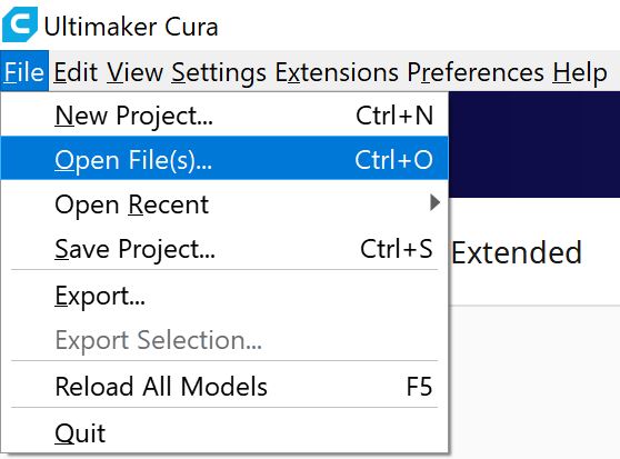
Open Ultimaker Cura and open the file from Step 1. This can be accomplished by going to File in the top menu, then Open File(s) and find the file.
Step 3 Now that the file is open, there should be three components. These components are the bottom plate, dielectric, and top plate from top to bottom. Select one of these three components to customize by choosing it from the Object list tab in the bottom left of the screen, or by clicking on the component shape in Cura.
Step 4
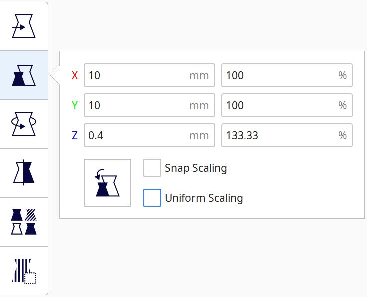
Change the size of the plate. This can be done by going to the Scale (S) option on the left hand menu. Deselect Uniform Scale to change plate surface area and plate thickness individually.
Step 5
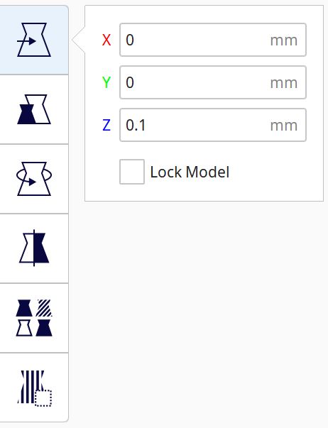
Change the positioning of the plate. This can be done by going to the Move (T) option on the left hand menu. Center all plates at x = 0mm and y = 0mm. For z, keep the bottom plate slightly above the build plate (z = 0.1mm or so). For every plate above the bottom plate, add the thicknesses of plates below it and the 0.1mm gap initially defined.
Repeat steps 4 and 5 until the desired structure is acheived.
Step 6
Slice the design and save under a name of your choice as a .gcode file.
Step 7 Follow steps 1 through 4 from the previous section (Print original Monti provided sensor) to complete the print, changing the file names there for the ones chosen by you.