Preparing Electrical Contacts
Materials
A Printed sensor
A spatula or other similar dull and flat blade
Electrical wire (Recommended: AWG 30 wire)
Conductive adhesive (Conductive tape, conductive paint or epoxy. conductive paint recommended for price to performance ratio)
Painter’s tape
Procedure
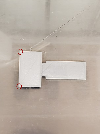
Using a spatula or other dull blade, pry the sensor of the print bed at the corners of the sensor base (highlighted in the image below).
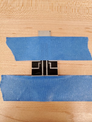
Place the sensor on a flat table with an easily cleanable surface. Tape the sensor to the table using standard painter’s tape, as shown in the image below.
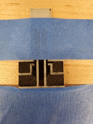
Using a flat blade, gently scratch the surface of the electrical contacts. The roughened surface will allow for better adhesion to conductive paint or other adhesive.
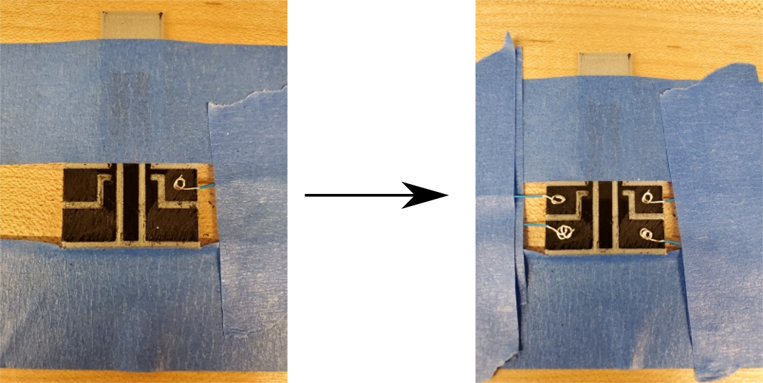
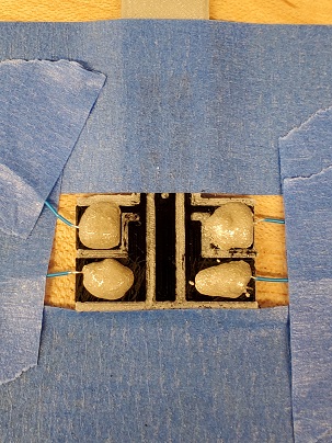
Cut four approximately equal lengths of solid core electrical wire. Strip an equal length off each side of every wire. Curl one end of each wire into a U or loop shape. Place the curled end of each wire on the middle of each contact pad. Tape the wire to to the table, as shown in the image below, to secure the wire position.

Note: ensure that each wire is in direct contact with the electrical contacts, as failure to do so could result in poor electrical contact or open circuits.
Apply a small amount of conductive paint to each wire as per section Using Conductive Paint.
Note: Ensure that you are familiar and comfortable with the use of conductive paints. Applying too much can cause the paint to spread out and connect to another another electrical contact. This will short circuit the sensor, causing it to become non-functional.
Let the conductive paint dry at room temperature for 12 hours or as per instructions provided by the conductive paint manufacturer.