Example Process Flow
This section further explores the Pithon platform for 3D printed sensors.
How do implementations of the Pithon platform get made? How will you produce 3D printed sensors for yourself? What does the process look like? To answer these questions, we will walk through an example process flow.
The process begins with continuous fabrication, building your design from the ground up using conductive and structural plastics.
First, electrically conductive traces are deposited onto the 3D printing surface. These will make up the electrical terminals and sensing elements of your accelerometer and temperature sensor:
.png)
The conductive traces are surrounded with with what will become your enclosing structure of arbitrary size and shape:
.png)
The conductive traces are covered as required with more of their enclosing structure:
.png)
A cantilever beam for your accelerometer has been printed:
.png)
Now, the 3D printing process continues – layer by layer – leaving more space for a cavity:
.png)
By this point, the conductive 3D printing filament would have been swapped out for dissolvable filament for use as a temporary filler material to support upcoming layers. Alternatively, the cavity walls would slope both upward and inward to support subsequent layers, meaning that you wouldn’t have to use a temporary support structure.
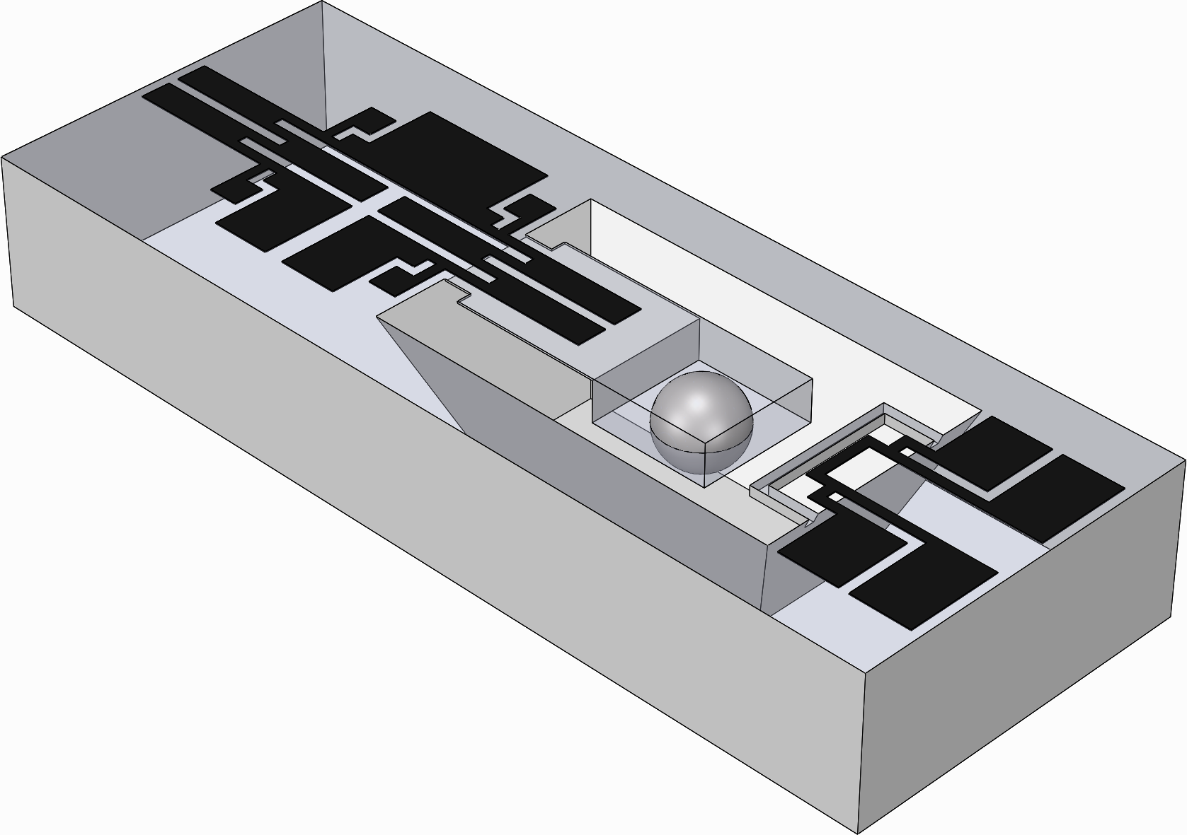
You press-fit a steel ball into the space provided at the end of your accelerometer’s cantilever beam:
.png)
This will make it especially sensitive to acceleration. This weight is a proof mass. Because it is metallic, your accelerometer can also be used as a magnetic field sensor.
The cavity is covered with the rest of your arbitrarily shaped enclosing structure:
.png)
Note that especially by this point, the 3D printed part would be partially made up of a lattice – this is the infill pattern.
The 3D printing process of our part is soon complete.
You remove your part from the surface of your 3D printer. It was printed upside-down. This served four purposes:
Made it so that any problems with the conductive printing filament were detected early.
Made the conductive plastic adhere to the surface of your 3D printer better.
Improved the surface finish of your embedded sensors.
Allowed your sensing elements to be as thin as 60 microns, such as for your temperature sensor.
A Pithon accelerometer and Pithon temperature sensor have been embedded into your arbitrary part. This design, for example, can be readily used for evaluation purposes as part of the Pithon platform:
.png)
This is your embedded accelerometer:
.png)
When the whole part speeds up or slows down, its cantilever beam bends up or down depending on the direction and amount of the acceleration it experiences. The material making up the top half of the beam gets compressed or stretched, especially at its base and on its surface. This is why two strategically sized notches are placed in the base as shown. They ‘concentrate’ its mechanical stress toward its sensing element, which is at the beam surface. This makes it more sensitive to acceleration.
The accelerometer may also be calibrated as a force sensor or magnetic field sensor under certain conditions (see end of section Pithon Accelerometer).
This is your accelerometer’s primary set of conductive traces:
.png)
The zig-zag pattern in the middle is what forms its sensing element, a strain gauge, whose electrical resistance readily changes with mechanical strain. But the conductive traces’ resistance also changes with temperature and humidity.
This is where your accelerometer’s secondary set of conductive traces comes into play:
.png)
The secondary set can share an electrical terminal with the primary set and is its mirror image. But unlike the primary set, it isn’t on a flexible beam. Because of this, it isn’t sensitive to absent mechanical strain – just temperature and humidity. These two “environmental conditions” are shared by both sets of conductive traces. Since the primary set responds to acceleration and environmental conditions similarly, and this secondary set responds only to the same environmental conditions, the acceleration by itself becomes known.
This is your embedded temperature sensor:
.png)
It measures the temperature of the surrounding air. Its sensing element is so small that it can point out of your arbitrarily-shaped structure too – without getting in the way of anything. A kind of “guard rail” stops it from being damaged. Here, the sensing element is suspended midair in a cavity. Either case provides airflow.
This is your temperature sensors’ set of conductive traces:
.png)
The sensing element’s electrical resistance changes with temperature. A method called four-terminal sensing or Kelvin sensing is used to factor out temperature-dependent contact resistances.
Now, you put liquid conductive paint (or conductive epoxy) on the large contact pads formed by the conductive traces:
.png)
Before the conductive paint hardens, you bond wires to these contact pads:
.png)
Finally, you connect your physical implementation of the Pithon platform to your microcontroller as illustrated and, optionally, a different power source, such as a coin cell embedded in your 3D printed part.
.png)
Not shown: Minimal interface electronics.
The microcontroller takes care of signal processing and digitally transmits the calibrated acceleration and temperature to where the data is needed.
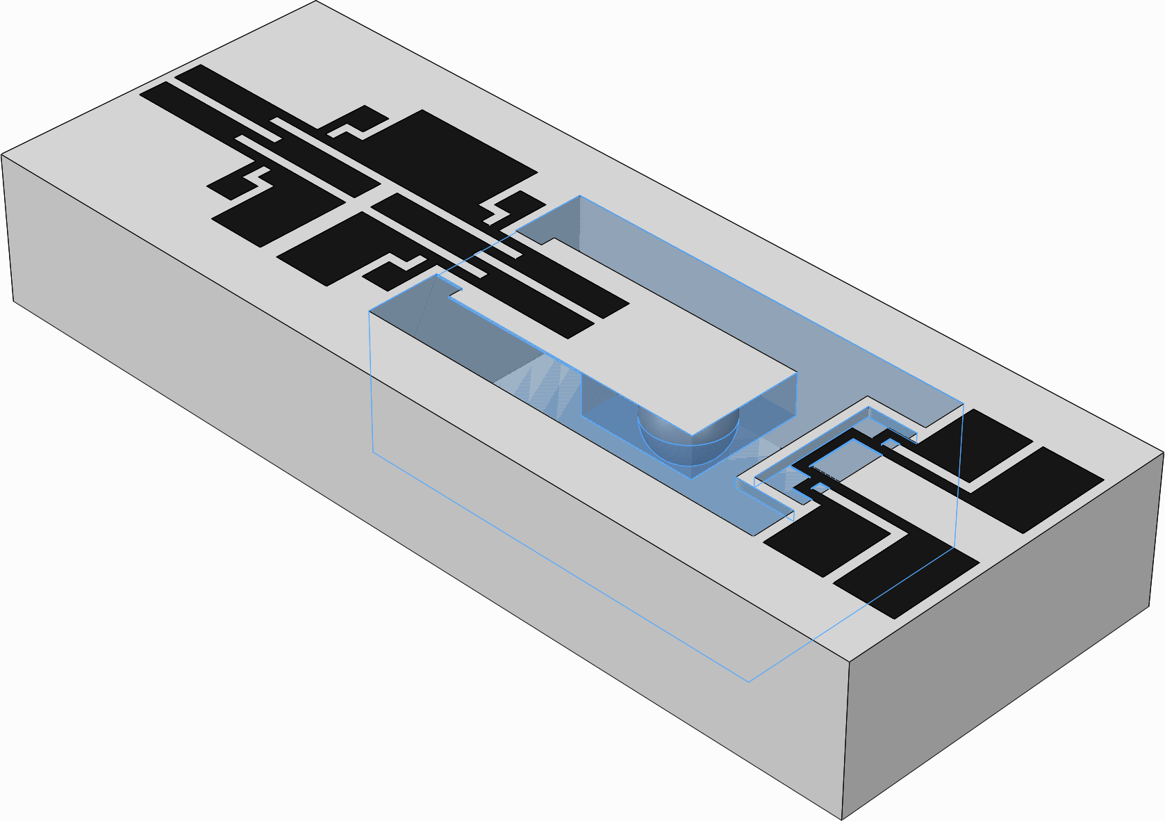
Using Filler Material
The following is a modified version of the Pithon implementation in the example process flow. It uses 3D printed filler material – dissolvable PVA filament – as a support structure (highlighted blue) for what becomes the base of the cavity.
Using Tapered Cavity Walls
The following is a modified version of the Pithon implementation in the example process flow. Its cavity has tapered walls to support subsequent layers, leaving potential for printing without a support structure. The top face of the enclosing structure is hidden to better show the cavity walls.